


Tin tức
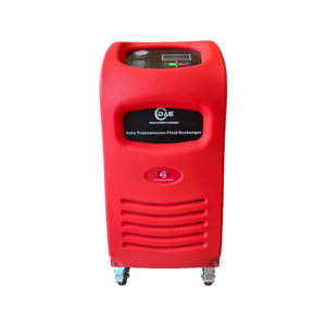
DAEQUIP AC66 OPERATION MANUAL
Th4
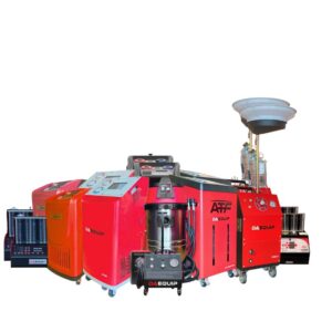
Congratulation on the purchase of the AC66
Refrigerant Processor
This is a very good investment you have made for your workshop. This system will help your technicians in achieving their best capability in diagnosing and rectifying air-conditioning issues, thus increasing productivity and profitability for your business. This system can be customized to suit each individual workshop needs. Our company would like to work with you as partners in your business to help you achieve maximum return on your investment, so please do not hesitate to contact us or our distributors, if we can be of any further assistance in relation to this equipment use and maintenance, or any air-conditioning related issues. We are always here to help you in achieving higher productivity.
AC66 is an ideal option for workshops that have limited equipment investment budget. Even economic, the machine is robustly built, with luxurious features such as color touch screen, amply database and patented oil separator/manifold. The unique design has facilitated quick load cell unlock, easy and economic maintenance (DIY maintenance recommended), self troubleshooting and convenient USB upgrade etc..
General safety
- The storage cylinder in this unit contains liquid refrigerant. Overfilling of the cylinder can cause violent explosion. Do not disable the overfill safety feature. Always keep the cylinder on the load cell platform whenever operating the machine.
- The operator must carefully read the instruction manual before any operation is performed. Incorrect operations could cause serious consequences, such as, improper A/C service, damage to automotive A/C system or damage to equipment.
- Only use cylinders which are recommended by the manufacturer and supplied with this equipment.
- Avoid inhalation of refrigerant or oil vapor/mist, read material safety instructions on refrigerant and oil package.
- Switch off and disconnect power cable from main supply before removing any cover or servicing the equipment, to avoid electric shock which can be very dangerous or fatal.
- Never use compressed air for leak testing the unit or vehicle A/C system!
- Wear safety goggles and gloves, to protect eyes and skin from contact with refrigerant. Coming in contact with liquid refrigerant can cause frostbite and blindness. If accidental contact is made with liquid refrigerant, wash effected area with plenty of fresh water and contact a doctor.
- Avoid using extension power cable than 1.5mm2 copper core.
- Keep gasoline or other flammable substances away from the equipment.
- Always operate unit in a well-ventilated area and away from artificial heat
Specifications
Ø Dimension:Package 700*500*1120mm; Unpacked machine 651*460*980mm
Ø Input power:AC220V±10%~50/60Hz,or AC110V±10%~60Hz
Ø Compressor power:3/8HP
Ø Average gas state refrigerant recovery speed (through charge/suction port):0.25Kg/min
Ø Hand valves free
Ø Recovery rate: 96%
Ø Vacuum pump capacity:60L/min, non-sparkle
Ø Accuracy of gas cylinder load cell:±10g
Ø New oil bottle capacity:250ml
Ø Used oil bottle capacity: 400ml
Ø Max. Pressure:20bar
Ø Charge speed:2Kg/Min(max.)
Ø 7 inch touch screen, full color
Ø High pressure gauge range:-1bar~40bar
Ø Low pressure gauge range:-1bar~22bar
Ø A/C database included
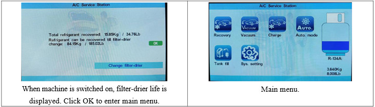
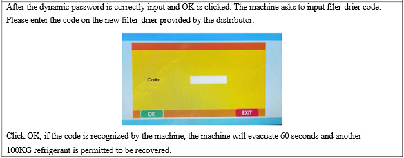
Ø Automatic service reminding. The equipment filter-drier life is designed to desiccate and recycle 100 KG refrigerant. Upon filter-drier life expires, the machine is automatically locked and a machine maintenance needs to be performed. A machine maintenance includes, but not limits to, filter-drier replacement, but also pump lubrication oil replacement, solenoid spool washer replacement, leak test etc..
Function
Main function
- Recovery: Recovers and purifies refrigerant from automotive A/C to equipment tank.
- Vacuum: Evacuates air and moisture from the A/C system. Upon completion of vacuum, the machine prompts to inject new oil into A/C through a hand valve.
- Charge: Charge refrigerant from equipment gas cylinder to automotive A/C system.
- Auto. mode: Performs the selected functions in a fully automatic sequence. The machine will stop automatically once all the selected functions have been completed.
System setting
- Language: Select operation language.
- Calibration: Calibration refrigerant gas cylinder load cells.
- Database: Enter automotive A/C database
- Unit set: Select metric or imperial units
- Empty container weight set: Set empty refrigerant gas cylinder.
- Component test: Test work status of solenoids, vacuum pump and compressor.
Part description
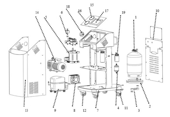
| 1)Refrigerant gas cylinder | 2)Refrigerant gas cylinder support plate | 3)Refrigerant gas cylinder load cell |
| 4)Drier-filter | 5)Manifold assembly | 6)Assembly of solenoid valve and check valve |
| 7)Base | 8)Condenser and cooling fan | 9)Compressor |
| 10)Back cover | 11)Front wheel | 12)Rear wheel |
| 13)Shell | 14)Vacuum pump | 15)High pressure gauge |
| 16)Low pressure gauge | 17)Touch screen | 18)Tank pressure gauge |
| 19)Oil bottle |
Operation preparations
Unlock load cells
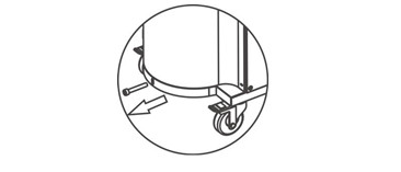
Remove the bolt that fix tank platform with chassis, to release tank load cell.
Fill equipment with refrigerant
(New equipment is empty, you need to fill the equipment with refrigerant and refrigeration oil)
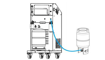
Connect either HP or LP hose with external refrigerant R134a or HFO-1234yf tank, and turn on the machine, select corresponding refrigerant type, run recovery to fill equipment with refrigerant. After one refrigerant tank is filled, fill other tank with its corresponding refrigerant. It is recommended to maintain both tanks at 3-6kg refrigerant.
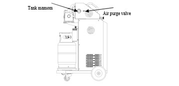
Air purge
It is recommended to purge the air in equipment tanks every day before turn on the machine. At left and right sides of machine, air purge manual valves and P-T chart can be found. Turn the valve to purge the air, strictly abiding by the pressure to be consulted in chart, corresponding to environmental temperature.
Equipment Connection (Recovery/Vacuum/Charge/Flush/Auto. mode)
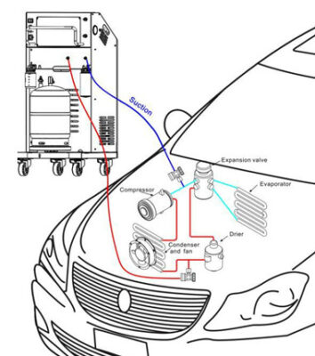
Warning: Except the situations clearly stated in the manual, during recovery and all other equipment operations, please maintain the vehicle engine and A/C off, otherwise unexpected damages may be caused.
Recovery
Empty used oil vessel before the recovery function is started.
Select “Recovery”
function icon in the main menu and click OK to start the process.
The recovery process recovers the refrigerant from vehicle A/C system, until a vacuum is achieved in the vehicle A/C system. Moisture, oil and foreign particles are separated from the refrigerant before it is stored in the internal refrigerant cylinder.
Vacuum (Vacuum and manual oil injection)
Select “Vacuum” icon in the main menu, set vacuum time and click OK to start the process.
The Vacuum process evacuates system, and makes system ready for oil injection and refrigerant charge. Although it is up to users to determine vacuum time, a longer vacuum process is recommended.
After vacuum, the machine prompts to inject oil by turning the new oil vessel hand valve at the machine side for fuel vehicles; For hybrid and electric vehicles, oil injection through the machine is prohibited, and it is recommended to inject oil with specialized oil injection tool.
Warning: PAG oil for fuel vehicle is electricity-conductive. Very few PAG oil being injected into hybrid/electric vehicle could bring about serious consequence.
Charge
Select “charge” icon and click OK to start the process.
According the vehicle being serviced, select “Normal charging” (Fuel vehicles) or “High voltage charging” (Hybrid or electric vehicles). In normal charging mode, hose flush (flush with liquid refrigerant to remove the oil residue inside the service hoses) is optional; while in high voltage charging mode, hose flush before oil injection and refrigerant charging is a must.
You can manually set charge amount with volume, or select “Charge by database” to set charge amount by car make and model.
You can choose to charge through high side, low side or both sides.
After charge and A/C performance is checked with engine started and A/C turned on. “Hose purge” is performed to help charge the refrigerant in service hoses into vehicle A/C system, to ensure better charge precision.
Auto. mode
Auto. Mode interface:
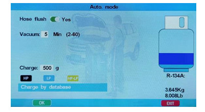
You can select “Auto.mode” to do full cycle of flush6S+only), recovery, vacuum, oil injection and charge. According the vehicle being serviced, select “Normal charging” (Fuel vehicles) or “High voltage charging” (Hybrid or electric vehicles). In normal charging mode, hose flush (flush with liquid refrigerant to remove the oil residue inside the service hoses) is optional; while in high voltage charging mode, hose flush before oil injection and refrigerant charging is a must.
In Auto. mode, the machine makes recovery, vacuum, oil injection (for fuel vehicles) and refrigerant charge in
sequence automatically, with data preset by users.
Empty used oil vessel before the process.
System setting
Select “system setting” icon and input PW 111111 (left and right arrow to move cursor, up and down arrow to increase/decrease number) to enter system setting menu. In system setting, “Language”, “Calibration”, “Database”, “Unit set”, “Empty container weight set” and “Component test” can be inquired or reconfigured.
Language
Can change operation system language.
Calibration
It is suggested to have only professional technicians to do calibration of load cells. The load cell calibration is very simple and fast, with just one step, 1kg weight calibration step.
Warning: Misoperation in calibration could bring about serious consequences to equipment or vehicle A/C system.
Database
Users can access database of refrigerant/oil volume of different car makes and models.
Record
Record total operations of recovery, vacuum, oil injection and charge. Can reset to re-record. A dynamic code is needed for access.
Unit set
To set metric or American imperial unit. The two numbers displayed in the bottom part of the interface are values of two tank load cells for reference.
Empty container weight set
The total load cell reading equals the sum of empty container weight and net refrigerant content value. Thus, increase/decrease empty container weight, can correspondingly decrease/increase refrigerant value displayed in the main operation interface.
Component test
Users can activate/des-activate different electronic component of the machine. This is for quick and easy diagnosis for troubleshooting.
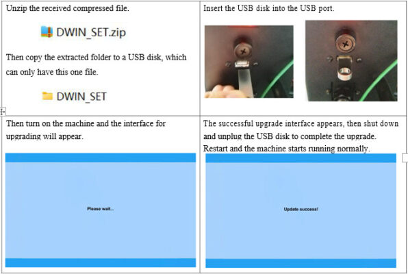
Update
Database update
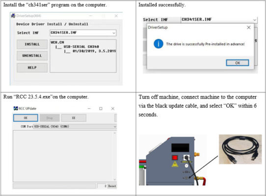
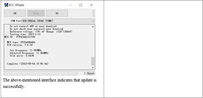
Main program update
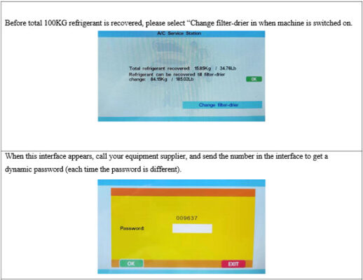
Service reminding & reset
Main troubleshooting
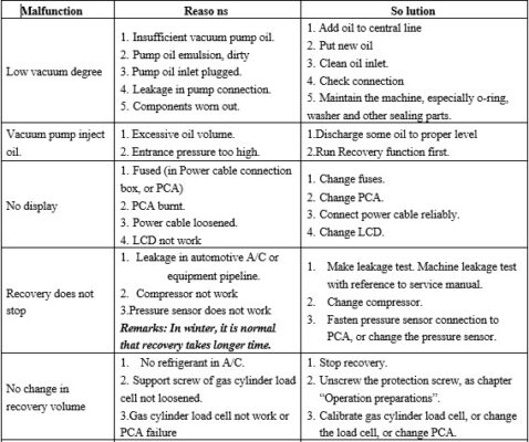
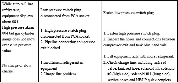
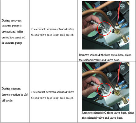
Remarks: Regular maintenance by specialized technicians may largely reduce machine failure.