Blog Kỹ Thuật, Chăm sóc xe
DAEQUIP 3197H OPERATION MANUAL
Th4
SAFETY INFORMATION
THIS EQUIPENT IS DESIGNED BE OPERATED BY QUALIFIED PERSONNEL.IT SHOULD ONLY BE OPERATED AFTER READING THE INSTRUCTION MANUAL AND UNDERSTANDING THE SAFETY RULES
• WEAR SAFETY GLASSES
• DO NOT SMOKE NEAR THIS MACHINE
• USE IN A WELL VENTILATED AREA
• READ AND UNDERSTAND THE MATERIAL SAFETY DATA SHEET
• IMMEDIATELY REPAIR ANY LEAKS IN THE MACHINE OR CONNECTORS
• IMMEDIATELY CLEAN UP ANY SPILLS
• DO NOT EXCEED THE PRESSURE FOR WHICH THE MACHINE IS SET.TO DO SO WILL CAUSE MACHINE DAMAGE, POSSIBLE PERSONAL INJURY AND VOID THE WARRANTY
1.UNCTIONING DESCRIPTION
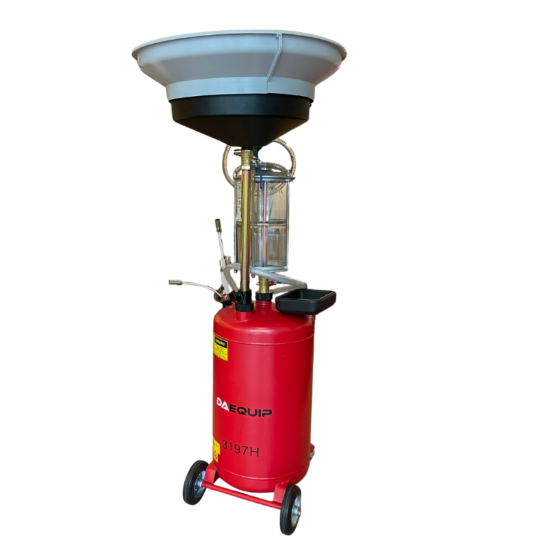
The machine are equipped with wheels and the user can move them easily and direct himself nearby the car that need service (wasted oil-suction, new oil filling, boby-cleanning).
The functions are below explanation to use.
3197H Component name

1、eccentricity pot 2、 one inch ball valve
3、oil pipelines 4、support 5、oil pipelines
6、fixed support 7、vacuum meter 8、vacuum generator
9、glass jar 10、Handle 11、accessories pot
12、tub 13、Wheel
Accessories:
1、operating manual 2、warranty card 3、one diameter: 8x8mm metal tube
4、one diameter:8x6mm plastic tube 5、one diameter: 8x6mm metal tube
6、one diameter:8x8mm plastic tube 7、one diameter: 8x10mm plastic tube
2 Technical parameters
Vacuum degree: negative 0-0.8PA
work pressure : 8-10PA
transparent window capacity: 10L
Oil storage capacity: 90L
medium: engine oilgear oil
N. W: 35kg
Oil suction pipe diameter: 5mm: 0.61m
oil pumping pipe diameter: 8mm: 1.61m
3 PACKAGE CONTENTS
Please inspect and look for damages from shipping when package is first received.if the unit is damaged in any way,please contact customer service and include pictures if possible.
In the package, you will find:
a)3197 H
b)Probes:5 pieces
c)OPERATION MANUA 1 pieces.
d) Tray 1 piece.
e) Chamber 1 piece
4 For the models with oil-display-transparent-tank it is necessary:
1) verify that the transparent-chamber has not been damaged during transporting(crack);
2)mount the transparent-chamber onto
the 701.tank and check it whether is appropriate seal;
3)Screw up the ring-nut by hands according the i(part with screwing-up by hands).

AIR-OPERATED OIL-CHANGER EQUIPPED WITH
OIL-DISPLAY-TANK
BASIC OPERATION FOR USE OF THE OIL-CHANGER
The depression of the chamber is a basic operation which allows an easier passage of the oil from the display chamber to the tank

1)COMPLETE VACUUM OF THE RESERVOIR CHAMBER
-Turn off all the cocks
of the aspirator and the cock connected to the probe.

-To connect the air-hose(8~10Bar)as position “2”, turn of the cock “3” (see fig.3) and start the depressurization of the tank up to 3/4of the scale of the vacuum-gauge “4”
(fig.3) see position of the index vacuum gauge, need time 3-4min.
2)MAX VACUUM OF THE RESERVOIR
Make sure that valve “2” is turned off and set the selector “1” on “B”.Now start the value of the reservoir for max 0,8Bar which is the max value of the acale of the vacuum gauge “4” (fig.3).turn off the cock “3” and release the air-hose from pos “2” (fig.4)
N.B. The air-filling must be made gradually.
The advantages
1)To reduce the air-consumption
2)A quicker depressurization
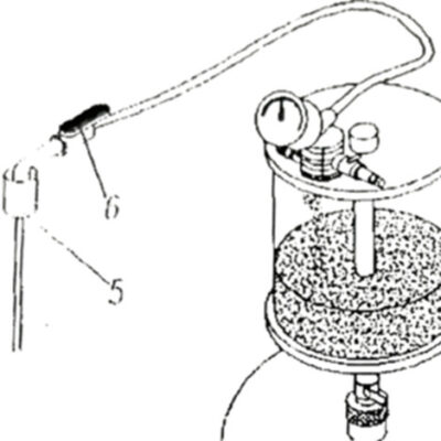
3)OIL-SUCTION
-Handle the cock “6” connected to the probe (fig * 0.4) and suck the oil and fill reservoir(max.capacity 61.)
NOTICE:During oil-suction use the more suitable probe “5” (fig .4)
TIME OF SUCTION WITH HOT-OIL
With probe diam.5mm.0.61/m
With probe diam.8mm.1.6l/m
It is possible to reach a vacuum of 0.75
bar
USE (TO WAYS)
A) To continuous compressed air connectby this way there is a constant depression capacity of the display tank,corresponding to 0.6 bar.
B)Device in autonomy (disconnected from the compressed air). In this way with the increase of the oil volume in the display tank to values near 51. the suction capacity (which reaches 6.5Lt and 1011.)-this in order to have a constant suction up to 10L.F
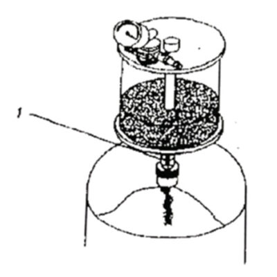
4)EMPTYING OF THE RESERVOIR AND TRANSFERING THE OIL INTO THE TANK
When oil is discharged from the transparent bowl into the lower reservoir without opening cock 1(fig.5)lt is not necessary to open the valve B only when the lower reservoir is depressurized
(when there is a vauum)
Notice:repeat the above operations to complete fill of the tank
5)Operation of connecting the oil
To place the machine to the location that is need to be connected the oil, Tuming off the cock “11” before the bowl is full. (fig.6)

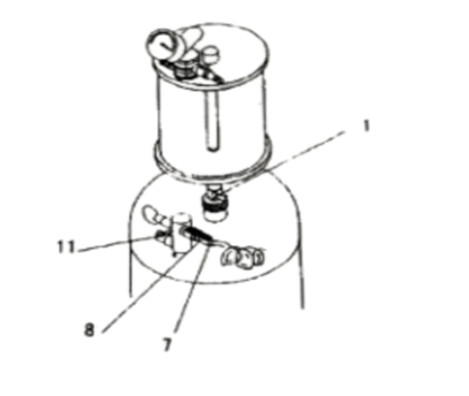
WARNING!!! The ball valve “1” must be closed before the tank is
added air.(Fig.6)
a) Connect the drainage-hose “9” inside a recovery-dnam for exhausted oils, turn on the cock “10” in emptying position (Fig.6)
b)Connect the air hose as per pos. “7” turn on the cock “8” (Fig. 7)
c)Fill air into the tank (max 1 bar)
d)When I bar is reached tum off the cock “8” if it is necessary
ejWhen the emptying is finished close cock “10”.
6.SAFETY DEVICES
A safety valve will release pressure when pressure is 30PSI the ejection process.
7.ORDINARY MAINTENANCE
a) Check leakage of the machine regularly
b) Pipe to pipe connection should be close together
c) It’s necessary to release the waste oil as soon as possinle in case of the corroding of tank.
Notice:Don’t forget to turn off the faucet when the tank is empty