


Tin tức
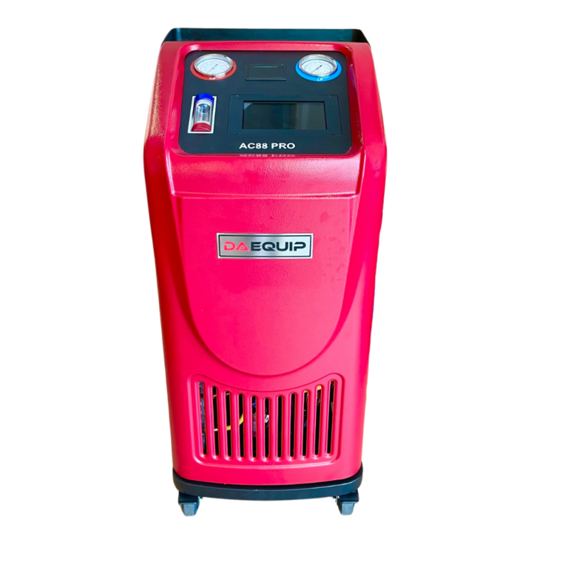
DAEQUIP AC88PRO OPERATION MANUAL
Th4
Congratulations on the purchase of AC88PRO Electronic Refrigerant Processor
This is one of the best investment you have made for your workshop. Due to that the company continues research and development and the joint effort of design, electronic and mechanical engineers including our sales representatives, air-conditioning manufactures and discussing the needs and issues of various workshop operators, in various countries around the world, we have manufactured one of the most user friendly, efficient and smart refrigerant processor. The AC88PRO refrigerant processor incorporates electronic intelligent using microprocessor platform. This system will help your technicians in achieving their best capability in diagnosing and rectifying air-conditioning issues, thus increasing productivity and profitability for your business. Our company would like to work with you as partners in your business to help you achieve maximum return on your investment, so please do not hesitate to contact us or our distributors, if we can be of any further assistance in relation to this equipment or any air-conditioning related issues. We are here to help you achieve your goal.
Specifications
Ø Dimension:Package 720*670*1190mm; Unpacked machine 630*560*1075mm3
Ø Input power:AC220V±10%~50/60Hz,or AC110V±10%~60Hz
Ø Compressor power:3/8HP
Ø Average gas state refrigerant recovery speed:0.25Kg/min.
Ø Recovery rate: 95%.
Ø Pressurization to speed up old oil discharge.
Ø Vacuum pump capacity:60L/min.
Ø Individualized filter-drier capacity: 600ml
Ø Accuracy of gas cylinder load cell:±10g
Ø Accuracy of oil bottle load cell:±5g
Ø Gas cylinder capacity:10KG
Ø New oil bottle capacity:250ml
Ø Used oil bottle capacity: 400ml
Ø Condenser and cooling fan included.
Ø Max. Pressure:20bar
Ø Charge speed:2Kg/Min(max.)
Ø 7’’touch screen, full color
Ø High pressure gauge range:-1bar~40bar
Ø Low pressure gauge range:-1bar~22bar
Ø A/C database included, update through USB port.
Ø Automatic service reminding. The equipment filter-drier life is designed to desiccate and recycle 100 KG refrigerant. Upon filter-drier life expires, the machine is automatically locked and a machine maintenance needs to be performed. A machine maintenance includes, but not limits to, filter-drier replacement, but also pump lubrication oil replacement, solenoid spool washer replacement, leak test etc..
Ø Thermal printer
Ø Heater band
Ø Optional: Vacuum leak test
Ø Optional:Flush
Ø Optional: Automatic air purge
Ø Optional: 120L/Min vacuum pump
Ø Optional: UV dye injection
Ø Optional: HFO-1234yf, difference including non-sparkle vacuum pump, 30 seconds pre-ventilation before machine is switched on, HFO-1234yf couplers etc..
Ø Optional: Refrigerant identifier for either R134a or R1234yf.
General safety guide
- This equipment must only be operated by qualified technicians.
- Read instruction manual carefully before operating this equipment. If there is anything you do not fully
understand, please contact your distributor or manufacturer. We like to help.
- The refrigerant storage cylinder contains liquid refrigerant under high pressure. Overfilling of the storage cylinder may cause violent explosion. Do not disable the overfill safety protection of this machine. Always keep the cylinder on the load cell platform whenever the machine is operating.
- Only use cylinder which is supplied with this equipment or recommended by the manufacturer.
- Always use this machine in a well-ventilated area, avoid inhaling refrigerant and/or oil vapors, always read material safety instructions of refrigerant and oil packaging, for related warning and care.
- Always switch off the machine and disconnect power cable before removing any covers or servicing this machine, to avoid electric shock which can be fatal.
- Never use compressed air to test for leaks on vehicle or this equipment!
- Wear safety goggles and gloves, to protect eyes and skin from contact with refrigerant. Liquid refrigerant when it comes in contact with the human skin or eyes will cause frostbite and/or blindness. If accidental contact is made with eyes or skin, wash the affected area with plenty of fresh water immediately and contact a doctor if required.
- Avoid using the machine in very hot or flammable areas.
- Store the machine in a well ventilated cool area when not in use.
- Avoid using extension power cable thinner than 1.5mm2 (10amp current carrying capacity).
- Keep gasoline or other flammable substances away from the equipment.
- For 1234yf machine, once a leak is detected in the unit, switch off the equipment by pressing the Emergency stop button and contact your distributor or service dealer.
Component identification
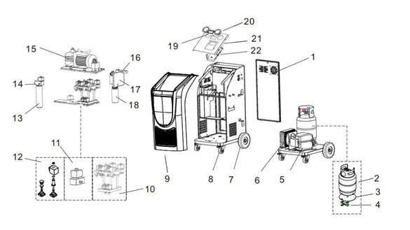
| 1)Back cover | 2)Refrigerant gas cylinder | 3) Gas cylinder support plate |
| 4)Gas cylinder load cell | 5)Compressor | 6)Condenser and cooling fan(optional) |
| 7)Rear wheel | 8)Front wheel | 9)Front cover(plastic) |
| 10) Manifold assembly 1 | 11)UV manifold | 12)Assembly of solenoid valve and check valve |
| 13)Drier-filter | 14)Manifold 2 | 15)Vacuum pump |
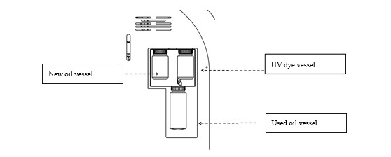
| 16)Oil bottle load cell | 17)Oil bottle support | 18)Oil bottles |
| 19)Printer | 20)Pressure gauges | 21) Upper cover |
| 22)PCA | ||
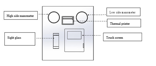
Control panel
Left view
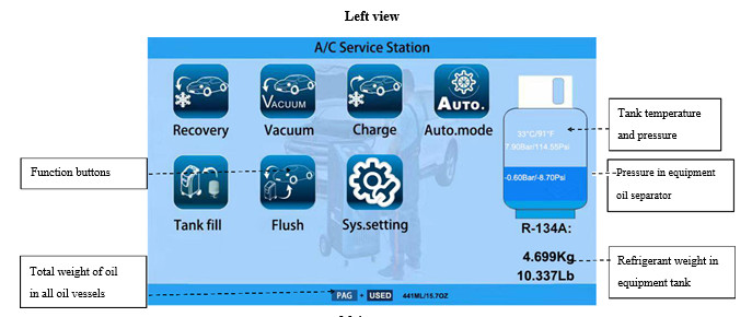
Main menu
Function description
Main functions
- Recovery: Recovers and purifies refrigerant from automotive A/C system and it is then stored in to the machine internal storage cylinder for re-use.
- Evacuation: Removes air,debris and moisture from the vehicle A/C system, with electronic vacuum leak detection test as optional function.
- Charge: Inject PAG oil (UV and POE injection as optional) into A/C loop. Followed by refrigerant charge into A/C loop.
- Tank fill: Transfers liquid refrigerant from an external cylinder to the machine internal storage cylinder.
- Flushing: With this unique flushing system, the machine will extract all compressor oil from automotive A/C system. Since A/C additives (such as UV dye, leak stopper and cooling booster) and contaminants (moisture, metal and rubber particles etc.) are mainly mixed or dissolved in compressor oil, flush is very important not only for A/C routine maintenance, but also necessary when an A/C part is replaced.
- Fully automatic function selection: The machine will perform all the selected functions in a fully automatic sequence. The machine will stop automatically once all the selected functions or function have been completed.
System. settings
- Language: Selecting language.
- Calibration: Calibrate refrigerant cylinder load cell, oil vessels load cells, pressure transducer and temperature sensor.
- Vehicle database: The machine stores a large number of vehicle makes and models, with manufacturers’ recommended refrigerant and oil charge quantities.
- Unit settings: Selecting metric or imperial units of measurement. All sensor values displayed in this interface for equipment diagnosis purpose
- Tare weight setting: Set empty refrigerant cylinder or refrigeration oil zero (tare) weight.
Preparations before operation
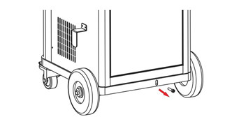
1. Unlock tank load cell
Unlock the load cell , by removing the safety locking bolt as shown below and save the bolt for future use. PLEASE NOTE, whenever transporting the machine, re-fit the safety locking bolt to avoid damage to the load cell.
2. Tank fill
Use the adaptor fitting, to connect either HP or LP service hose (red or blue) to external refrigerant cylinder liquid port which you will be transferring the refrigerant from. If the refrigerant cylinder has only, One valve and one port, invert the cylinder as shown below. If the cylinder has,
Two valves one port, leave the cylinder upright and open the liquid valve only, if the cylinder has,
Two valves and two ports, connect the adaptor to the liquid port, leave the cylinder upright and open liquid valve on the cylinder. Set the amount of refrigerant to be transferred into the machine storage cylinder, once the selected amount of refrigerant has been transferred, the machine will instruct the technician to close the liquid valve on the external cylinder. The machine will then recover the remaining refrigerant in the service hose which is connected to the transfer cylinder and it will then stop automatically. For more details please refer to “Tank fill” in the operating procedure chapter.
3. Non-condensable purge
Manual (basic): The manual air purge valve is located at equipment side, (with reference to chapter “Component identification”). Please refer to Pressure-temperature chart and tank pressure, turn the valve purge the non-condensable till proper pressure is obtained in the tank.
Automatic (Optional): After machine enters main menu, it automatically makes air purge in 10 minutes according to the ambient temperature and tank pressure of the machine.
Operating procedure
Recovery function
For HFO-1234yf system, refrigerant identification is necessarily processed. Only when the purity of refrigerant is above 98% the recovery is allowed.
Check and empty the used oil vessel before the recovery process is initiated.
The recovery process removes refrigerant from the vehicle A/C system, until a vacuum is reached. During this process, the refrigerant is purified from any moisture, oil and foreign particles. The processed refrigerant is then stored in the internal storage cylinder of the machine, ready for re-use. If any oil is recovered during this process, the oil will be discharged into the used oil vessel. After the first recovery has been completed, the machine will pause for 3 minutes, to check if there is any refrigerant left in the vehicle A/C system. Recovery will start again automatically if there is a pressure rise during the 3-minute pause. At the completion of recovery, the machine will display and print the total amount of refrigerant recovered and oil if any.
Evacuation function
Select “Vacuum” , evacuation is performed to further remove air and moisture from the vehicle A/C system, making it ready for oil injection. Evacuation time can be set from 2 to 60 minutes. If the machine has vacuum leak test function, vacuum test can be selected to effect 10 minute vacuum leak test.
Charge
Select “charge” icon and click OK to start the process.
According the vehicle being serviced, select “Normal charging” (Fuel vehicles) or “High voltage charging” (Hybrid or electric vehicles). In normal charging mode, hose flush (flush with liquid refrigerant to remove the oil residue inside the service hoses) is optional; while in high voltage charging mode, hose flush before oil injection and refrigerant charging is a must.
Oil (PAG, or POE if equipped) and UV (optional) volume can be set by technicians. Note, PAG is electrically conductive, and may largely influence cruise range of HV or EV given it is injected to high voltage vehicles mistakenly.
Refrigerant charge amount can be set by the technician, or by selecting car make and model in the database.
Refrigerant can be charged through high side, low side or high and low side.
Note, vehicle A/C system should be switched on when charging through the low side of the vehicle A/C system. Note, if charging is selected from high and low side simultaneously, care must be taken. After charging function is completed and before starting the engine and switching on the A/C system, turn the compressor hub several times by hand to expel any liquid refrigerant that may have accumulated in the compressor compression chambers during the charging process. Not performing this process can damage or destroy the compressor.
Tank fill
Please note, refrigerant identification is highly recommended before transferring refrigerant in to the machine internal storage cylinder, by using a reliable refrigerant identified.
Select Tank fill to fill or add refrigerant into machine storage cylinder. It is recommended to maintain 4-6 kg refrigerant in the machine internal cylinder at all time, to guarantee better charging and flushing operations. During the refrigerant cylinder filling process the machine will display to the technician to close hand valve on the external cylinder, the machine will then recover the rest of refrigerant which is left in the transfer service hose and internal pipelines.
The minimum tank fill set value is 0.5kg.
The maximum tank fill set value is the calculation result of 8kg (80% of tank allowable maximum weight) minus amount of refrigerant the tank contains ( For example, if there is 2kg refrigerant in the equipment tank, the maximum tank set value is 6kg).
Flushing function (optional)
For HFO-1234yf system, refrigerant identification is necessarily processed. Only when the purity of refrigerant is above 98% the recovery is allowed.
Please note, empty used oil vessel before starting this operation.
Flushing function is performed to completely extract compressor oil from A/C system, thus contaminants such as acidified substances, moisture and other foreign particles will also be extracted together with oil.
During the flush, refrigerant flows in forward direction (charge liquid refrigerant from A/C low side to dissolve compressor oil, and at the same time recover from the high side) and reverse direction (reverse direction means charge from high side and recover from low side, in reverse from normal A/C flow), each direction lasts certain period of time. Flush time can be set corresponding to refrigerant amount in system. For example, A/C system with 500g refrigerant, flush time is recommended to be set at 30 minutes, while 60 minutes can be set for system with 1kg or more refrigerant. Flushing refrigerant will be recovered and purified automatically, at the end of the flushing process and stored in to the storage cylinder, ready for re-use.
For some A/C system equipped with evaporator solenoids or electronic expansion valves, which are normally closed when the vehicle A/C is off, it is recommended to activate the solenoid and TX valves with proper diagnostic scanner or remove and bridge these valves with the appropriate bridging fittings. Not performing the above, refrigerant flow is restricted and flushing efficiency can be affected.
For multi-flow condenser, the oil in the condenser may not be flushed out completely.
Please make sure at least 4KG refrigerant in equipment, or flush is not permitted to run.
Automatic function mode
Please note, empty used oil vessel before starting this operation.
You can select “Auto.mode” to do full cycle of flush(optional), recovery, vacuum, oil injection and charge. According the vehicle being serviced, select “Normal charging” (Fuel vehicles) or “High voltage charging” (Hybrid or electric vehicles). In normal charging mode, hose flush (flush with liquid refrigerant to remove the oil residue inside the service hoses) is optional; while in high voltage charging mode, hose flush before oil injection and refrigerant charging is a must.
In Auto. mode, the machine makes recovery, vacuum, oil injection (for fuel vehicles) and refrigerant charge in
sequence automatically, with data preset by users.
Empty used oil vessel before the process.
System Setting
Input password 111111 to enter “System. Setting”. In system setting, Language, Calibration, Database, Unit set, Empty container weight set, Component testing and owner information will be displayed or reconfigured.
Calibration
It is recommended to have professional technician only to perform calibration of load cells, pressure transducer and temperature sensor.
Warning: Not calibrating the machine correctly can have serious consequences on the machine and/or vehicle A/C system.
Database
The technician can access database of refrigerant, oil volume of different car makes and models.
Unit settings
To set metric or imperial unit of measurement. In the interface of “unit set”, values of each sensor of the equipment are displayed for equipment diagnosis purpose.
Empty container weight set
The total load cell reading equals the sum of empty container weight and net refrigerant/oil content value. Thus, increase/decrease empty container weight, can correspondingly decrease/increase refrigerant/oil value displayed in the main operation interface.
Component test
The technician can activate and deactivate different electrical component of the machine. This is for quick and easy diagnosis and troubleshooting.
Please note:
Only qualified technician (with special password) is allowed to access this function, not performing this test correctly could cause damage to the machine or injury to the operator.
Caring for your equipment
Keep your equipment clean and well maintained at all times.
Keep service hoses stored on the storage adapters when not in use, to avoid dirt and dust contaminating the internals of the couplers which will then end-up in the vehicle A/C system, which can cause serious system malfunction.
Always clean vehicle A/C system service ports before connecting machine quick couplers on to the service ports.
Keep the system stored in a clean area and away from direct sunlight and artificial heat source, when not in use.
Perform regular services on the system as recommended by the manufacturer. Ignoring and skipping services will deteriorate the integrity of the machine.
If the machine is used on badly contaminated A/C systems frequently, it is recommended that more frequent vacuum pump oil changes are made and main filter replacements are performed. Contaminated vacuum pump oil will cause the vacuum pump to corrode badly internally, which eventually the vacuum pump will fail. Contaminated main filter will diminish the refrigerant purity.
Do not bump or move the machine when the technician is in the process of charging a vehicle, this can affect the charging accuracy.
If the machine is bumped or knocked down accidently, check the calibration and that there are no leaks internally.
DO NOT use compressed air to test for leaks.
If the technician is not sure on the correct way of operating the machine, please do not hesitate to contact your distributor or manufacturer. We always like to help you.
Update
Database update
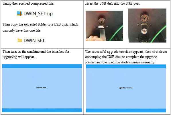
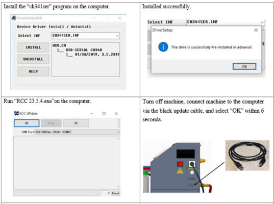
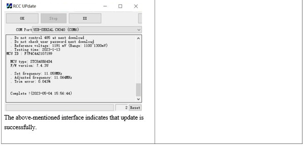
Main program update
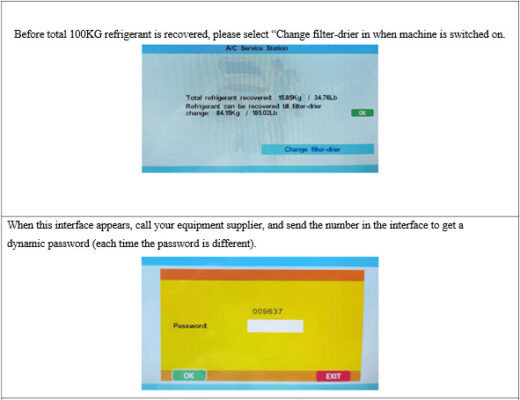
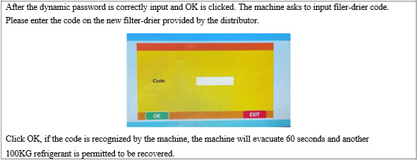
Service reminding & reset
Packing list