


Th4
Gas điều hòa ô tô là gì?
Điều hòa là trang bị thiết yếu trong khoang nội thất giúp lưu thông không khí, mang lại cảm giác thoải mái cho người dùng. Cần tìm hiểu về cách nạp ga điều hòa ô tô kịp thời để đảm bảo hiệu suất hoạt động của bộ phận này.
Gas lạnh hay môi chất là chất trao đổi nhiệt trong trạng thái tuần hoàn của hệ thống điều hòa trên ô tô. Gas điều hòa có nhiệm vụ hấp thụ nhiệt khi bay hơi và giải phóng nhiệt khi hóa lỏng giúp làm mát không gian khoang cabin.
Khi thừa hoặc thiếu gas lạnh, điều hòa hoạt động kém hiệu quả, tiêu tốn nhiên liệu có thể dẫn tới những hư hỏng trong hệ thống làm mát. Vì thế, các chuyên gia ô tô khuyến cáo nên bảo dưỡng định kỳ gas điều hoà sau 1 năm sử dụng hoặc sau 20.000 – 30.000 km vận hành. Khi phát hiện điều hòa có vấn đề, cần kiểm tra lại lượng khí ga. Nạp thêm hoặc thay gas mới để đảm bảo hệ thống điều hòa được hoạt động tốt nhất.
Cách nạp gas điều hòa ô tô
Nếu gas cũ – mới lẫn lộn sẽ gây nhiễu gas, làm giảm tuổi thọ của hệ thống điều hòa ô tô. Để tránh tình trạng này người dùng cần thực hiện hút chân không, đẩy hết không khí, độ ẩm và gas cũ ra ngoài tạo môi trường sạch trước khi nạp gas điều hòa ô tô mới.
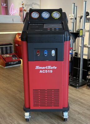
Dụng cụ để hút chân không gồm máy hút và đồng hồ đo áp suất. Trong đó, máy hút chân không có nhiệm vụ hút sạch tạp khí trong bình, còn đồng hồ đo áp suất sẽ kết nối giữa máy hút và dàn nóng điều hoà để theo dõi độ chân không trong hệ thống.
Đầu tiên, người dùng lắp máy bơm chân không, mở cả 2 van cao áp, thấp áp và bơm. Nếu thông số của đồng hồ đo thấp áp nhỏ hơn 750mmHg thì cần kiểm tra xem gas có bị rò rỉ hay không. Lúc này, nên tắt điều hòa để hạn chế khí ẩm lọt vào hệ thống, mở cửa kính để tránh tình trạng ngộ độc khí gas bị rò rỉ và nhanh chóng đưa xe vào gara để kiểm tra, sửa chữa.
Sau hút chân không là công đoạn nạp gas vào hệ thống. Đầu tiên cần lắp van, đục lỗ nắp bình gas và xả khí có trong đường ống giúp giảm áp suất bình chứa, tránh tình trạng bị thủng. Ngoài ra, người dùng cần kiểm tra khớp nối của ống nạp – nơi gas lạnh đi qua đã được siết chặt hay chưa, tránh thất thoát hơi lạnh và ngăn độ ẩm và không khí tràn vào ống nạp.
Với bước nạp gas cao áp cần lưu ý không vận hành động cơ, van thấp áp đóng hoàn toàn, van cao áp mở hết cỡ để đảm bảo an toàn.
Khi nạp ở van thấp áp, công tắc gió phải ở vị trí HI, bật công tắc A/C, mở hết công suất máy lạnh (chế độ MAX COOL), mở toàn bộ cửa xe và theo dõi thông số đồng hồ. Nếu thấp áp đo được ở mức 1,5 – 2,5kgf/cm2 và cao áp ở mức 14 – 15kgf/cm2 là dấu hiệu cho thấy gas đã được bơm đủ. Không nên bơm gas quá ngưỡng cho phép bởi điều này khiến áp suất gas trong hệ thống quá cao, máy nén hoạt động ở chế độ quá tải, ảnh hưởng đến chi phí hoạt động và khả năng làm mát của hệ thống điều hoà.ộ độc khí gas bị rò rỉ và nhanh chóng đưa xe vào gara để kiểm tra, sửa chữa.
Khi nạp đủ lượng gas cần thiết, chủ xe tháo dụng cụ nạp và mở máy, bật điều hòa kiểm tra khả năng làm lạnh. Nếu hơi lạnh không như mong muốn thì cần kiểm tra lại nguyên nhân khác và có hướng khắc phục kịp thời, tránh làm hỏng hệ thống điều hòa của xe.
Ngoài thực hiện các bước nạp gas điều hoà ô tô theo đúng quy trình, chủ xe nên lưu ý chất lượng gas. Hiện nay, gas lạnh có hai loại là R12 và R134a (R1234Yf khá ít chủ yếu là trên các siêu xe). Trong đó, R12 có nhiều hợp chất gây hại cho sức khỏe và có nguy cơ phá huỷ tầng ozon. Còn R134a dễ bay hơi và hoá lỏng, không mùi, không gây cháy nổ, không ăn mòn, không độc hại nên được sử dụng phổ biến hơn. Lựa chọn gas điều hòa rõ nguồn gốc, thực hiện nạp gas đúng quy trình sẽ đảm bảo hiệu quả làm mát và tăng tuổi thọ cho điều hòa.